
I recently went over the basic design of my printer and this post I wanted to go over some decisions for the Z Axis system. There are many different designs for the bed and how to move it out there and I wanted to research some of the examples out there to understand the best method for this printer.
Bed Design
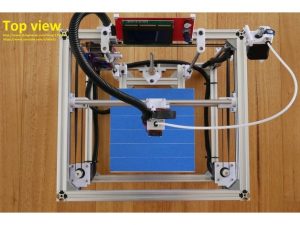
With some past research, I am most interested in a CoreXY Kinematic system with a Bowden style extruder. The Hypercube by Tech2C is a great build log series that goes into great detail on the process of making a CoreXY 3d printer. I love practically everything about this design except for the mechanics for the bed. The bed is lifted by a single lead screw, stabilized by 2 linear guide rails.
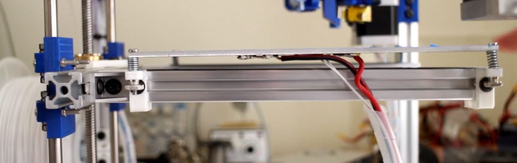
Tech2C revisits the build platform, explaining how the bed has a decent bit of sag and bounce as it is driven up and down. He comes up with a great solution to better mechanically stabilize the bed. You can watch the build log video here.
Still, just being driven from one side seems problematic to me. With how cheap some of these parts are, why not expand the system? I was hoping to find some sort of upgrade that takes advantage of multiple lead screws rather than just one. Multiple lead screws are seen in common designs like the Prusa i3 or Ender 3 (direct Cartesian style printers) which have a lead screw on either side of the build platform to drive the gantry up and down. Of course these have to lift a lot more weight, but the idea of stability is still there. If you want to read more on the topic, you can check out my post here.
Multi-Lead Screw
After a bit of research I found this upgrade post by ThijsRico on Thingiverse. He shows an upgrade that uses 3 lead screws tied together by a single GT2 Timing belt. These are all driven by a stepper motor attached by belt to the top of a single lead screw.
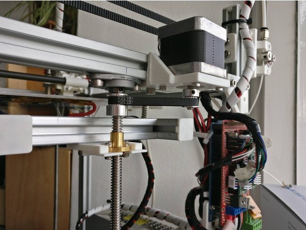
The things I like most about this design are it maximizes Z print space, allowing you to use as much of the lead screw length as possible. 3 lead screws give 3 points of constraint of the build bed allowing control over the plane of the bed. This is all good and well, but I still have multiple concerns with using 3 lead screws:
- 3 lead screws but no guiding rails
- Driving 3 lead screws with a single stepper motor
- Where/how to drive the lead screws with the stepper
You can see on the Thingiverse post there are 2 updates from the original post. The first update brings up the greatest weakness with this design, the lead screws are unable to constrain the build platform well in the XY axes, they are meant to drive specifically in the Z axis. He says he will incorporate 3 10 mm linear shafts to combat this. The second update tells how the linear shafts didn’t solve his problems so he went to a belt driven design. I have no interest in a belt driven design that I detail in my basic mechanics post.
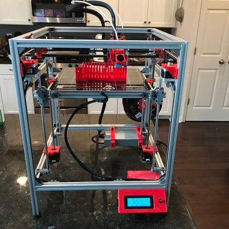
This design was also apparently remixed by another user, PixelMagic, for a design that implements 4 lead screws, called the PixelCube:
This design using 4 lead screws, no linear guides. This should suffer the same consequences as the 3 lead screw design above. No complaints about it from PixelMagic. PixelMagic posted links to other printers that served as inspiration, so I took a look at some of those too.
Lead Screws and Linear Guides
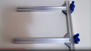
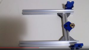
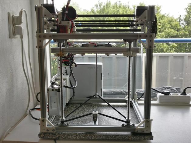
This is the Hypercube 300 by Adrianm1972:
I really like this design. 2 lead screws on either side with 2 linear stabilizers for each lead screw. Although its just using the 2 lead screws, I think this is a better idea than 3-4 free lead screws.
I really think the placement of the linear guides is key here as well. Since there are only 2 lead screws, you can constrain 2 axes, but the third axis is free to rotate. This rotational motion is then stopped by the nuts on the lead screws, which will cause a good deal of wobble and eventually wear down the lead screw due to the constant torquing forces on it. The linear guides are placed at the corners of the print bed to constrain as far out as possible on that axis. This helps restrict any wobbling force around those 2 lead screws as much as possible.
I think there is some experimentation to be done. Theoretically I could change up the amount of lead screws and linear guides relatively easily so long as I have the hardware for it. Since it all mounts between pieces of the frame and has the same distance to the bed frame, the parts should be relatively modular.
So Which Design
For the time being I would like to try 2 lead screws with 4 linear guide rails since that seems to be a more confident assembly and test different configurations as I would like to find the combination that works the best so I can post my findings to the community. 2 lead screws gives plenty of lifting leverage while having adequate linear guides to ensure as flat and just as important, stable bed platform. Its a decent amount of hardware, but I think worth it to ensure a sturdy bed.
Next posts will be going over some designed parts and detailing some of the build process thus far!