
This post will be going over basic design and materials. I will be laying out some basic dimensions and will start to go over what parts need to be custom designed and 3d printed to fit all this together. The majority of my design is based off the HyperCube CoreXY printer by Tech2C, I have talked about this design before and it is a great inspiration for my own design. I will be referencing his design quite a bit, but will not be afraid to stray from it for my own needs. Following posts will be detailing exact parts purchased thus far, specific design decisions, and individual designs for parts that need to be printed.
I am going about this design a bit relaxed, ensuring the main dimensions of the frame then having everything fit within those frame dimensions. Taking this relative approach I think will save me a lot of time and stress as I work bottom up. Once I get the main frame together I can also take physical dimensions of things, making it much easier to figure out dimensions. Maybe not the smartest idea, but it’s cool, what could go wrong…..
Basic Layout
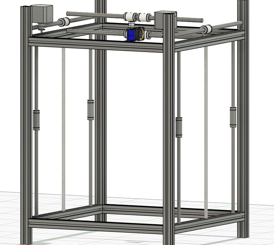
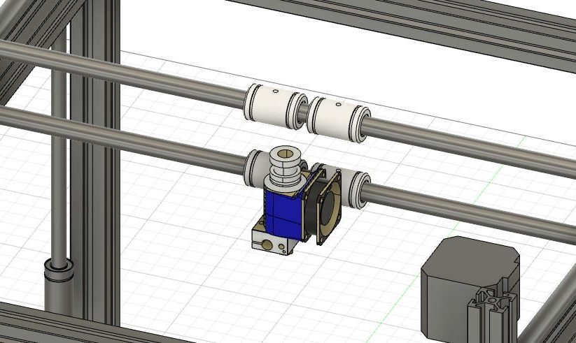
I have started laying out some basic spacing in Fusion 360. I haven’t started designing individual parts yet since I am still finding exactly where I can source specific parts and materials from, but now that I have all the parts I need and a realized form, I should be able to move on. Here is the basic spacing:
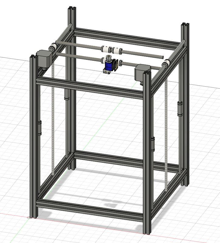
Frame
The frame will be made with 4 x 550 mm upright 2020 aluminum extrusions connected by 8 x 350 mm 2020 aluminum extrusions. The aluminum connecting the uprights will be 400 mm apart vertically (actually a little bit larger) from one another to accommodate the lead screws, which are 400 mm. The space below and above this 400 mm area will shift, but the only space at the top that is really needed is for the stepper motors to be placed upside down, so around 62 mm. That would leave around 68 mm for the power supply and other electronics from the lower connecting extrusion to the base of the printer (it will realistically be more than this because the print bed won’t go all the way down, but we will use any left over space to house electronics).
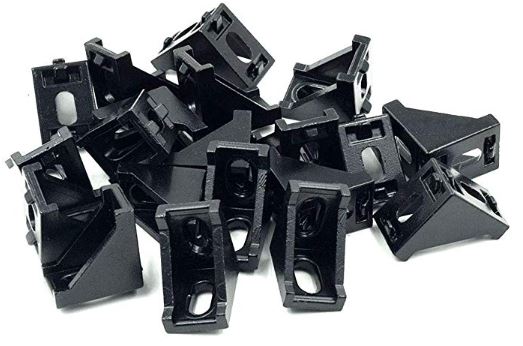
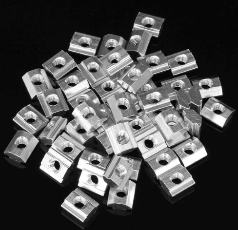
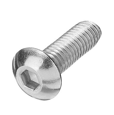
I plan to construct the frame with 90 degree angle brackets with T-slot nuts and 8mm M5 screws. This should make a super solid frame that holds and won’t wiggle loose. I am very concerned about getting everything as square as possible. This will largely be based on how square the cuts are made in the aluminum extrusion as well as how square the angle brackets themselves are, so I will have to keep an eye on this. More than likely though, they will be completely fine for the time being and I can always go back and print square brackets or cut some out in the future.
Z Axis Design
I plan to use 2 lead screws set in the middle of the frame with 2 linear guide rails on either side of each lead screw. I have done a bit of research into Z Axis assemblies that I will go over in a separate post since I had a bit to say about it.
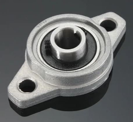
The lead screws will be mounted to the frame with bearing blocks. These let them sit flush to the frame and have free rotation. These lead screws will be connected by belt and pulley and driven by a single stepper motor. This would keep everything in sync with one another while keeping it relatively simple. I have 2 ways to drive the lead screws. One way being both lead screws are connected and a motor is connected to one of the lead screws, transferring the power through. The other is the lead screws and stepper motor are all tied together by a single long belt. I well test, we will see, but I don’t think it will make much difference since it doesn’t have to do much work.
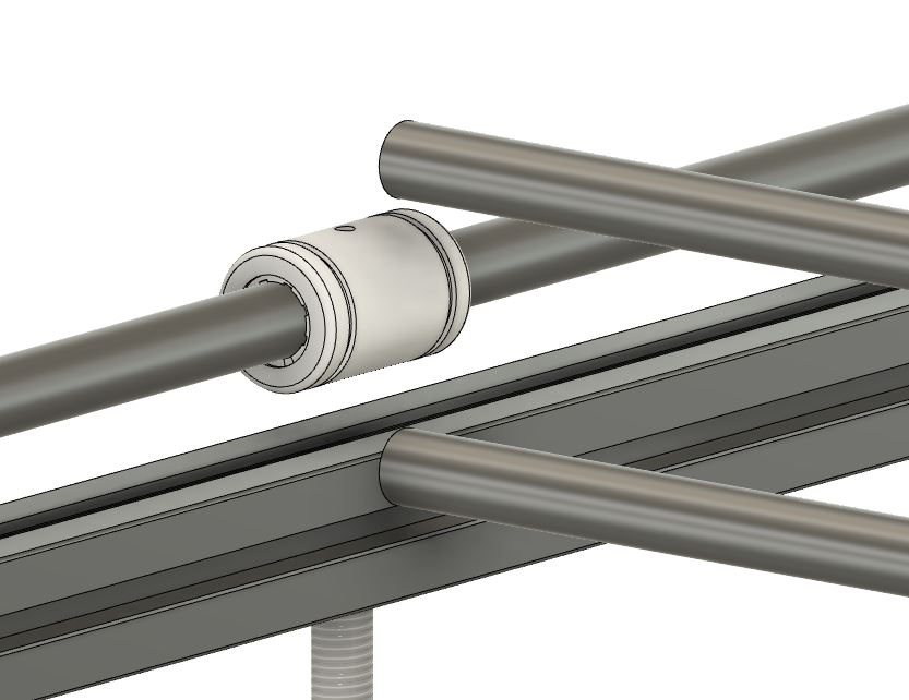
The the linear guides are 406 mm hardened chrome rods, precision ground to a metric G6 tolerance. Being a bit over-sized is a little annoying, hopefully I can get them to fit with the 400 mm lead screws since they will have a bit of leeway from the bearing blocks. But I can always cut a bit off, even if it would be really annoying.
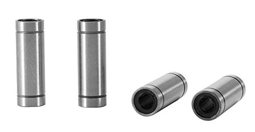
The linear guides will use LM8LUU linear bearings. This is the only place I use these bearings specifically. I plan to use polymer bushings for the rest of the printer (and the parts that move the most) since they are significantly more quiet and generally require little to no maintenance. I will be doing a bit of a comparison at some point more than likely since there is a bit to say about linear bearings/bushings and I have done a lot of reading on them.
Stepper Motor Mounts
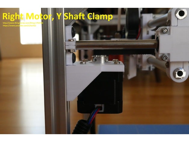
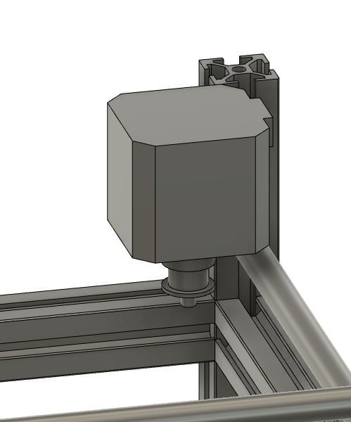
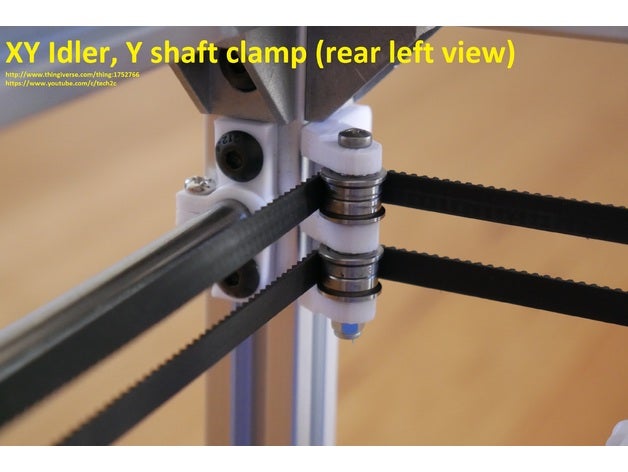
The stepper motors will be mounted upside-down to maximize space, that’s what I really liked about ThijsRico’s printer design. These motors each need a unique mount as one needs to be higher than the other due to the nature of the stacked belts in a CoreXY design. In the opposite corners of the printer there needs to be a holder for the idler pulleys to guide the belt around:
The mounts for the stepper motors and idler pulleys will be designed with as tight of tolerances as possible to maximize print space. Minimizing their footprint is very important but ensuring the part is strong and mounted in multiple places to ensure its stability is important.
XY Joiner
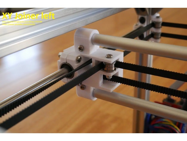
The idler and stepper mounts need to also be designed and placed in tandem with the XY Joiner to ensure they are properly spaced and line up since the belts should be fed pretty straight and square to make sure they don’t rub or anything and are free to move easily. They need to also accommodate the idler bearings and mine are a little larger than the one Tech2C uses as he uses 2 bearing seated against one another while I just bought regular idler pulleys. The XY Joiner will also mount the cross bars to hold the X print carriage.
Print Carriage
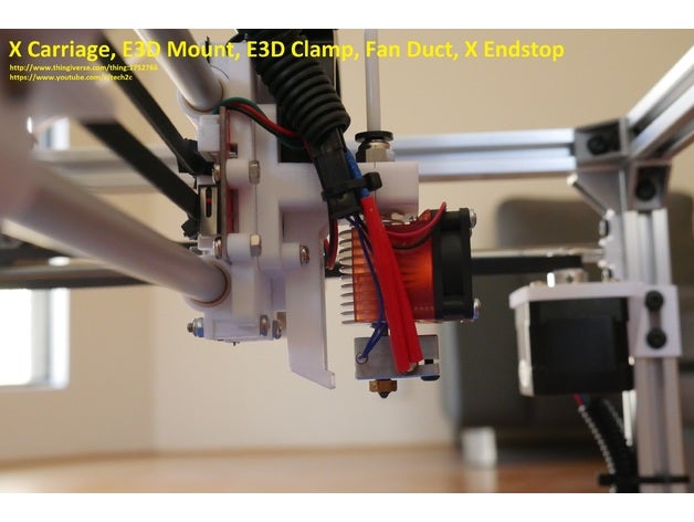
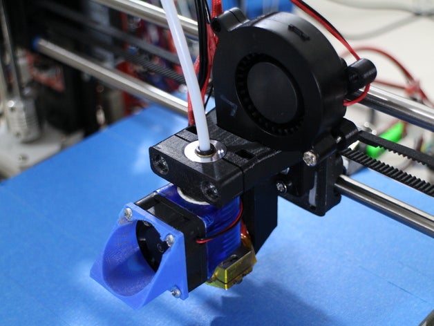
I have seen carriages with longer bearings, shorter bearings, multiple small bearings, etc. I’ve gotten enough bearings so that if I need them, I can put 2 on either rail or use less if I find I don’t need as many. I have bought the E3D V6 hotend since it is very common and reliable in the community. It is also quite simple to mount, just a sort of flange at the top that is easy to clamp down to. The cooling fan is also important to cool the layers as they are printed and are usually mounted at the top like shown in the middle image above. The design is pretty straight forward to mount components to the carriage, but mounting the belts and bearings to the back of the carriage is a little more complicated.
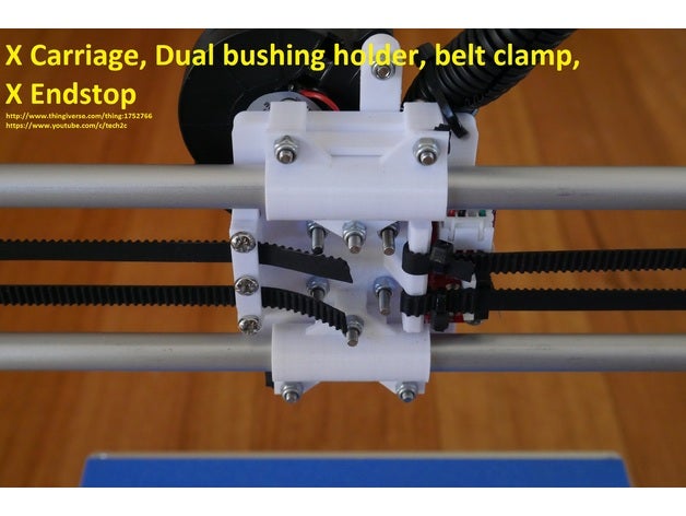
The belts have to be held on very tightly, obviously. Typically this is by folding the belt over on itself to lock it’s teeth together. The other side just clamps down on the belt so that it is easily tightened. All designs tend to look very similar for these carriages, so I will be using the carriage from the HyperCube as reference.
Print Bed
To be honest, I’m not really considering the print bed just yet. I have the electronics worked out so there will be enough power for it, but I will design it in as I go. It seems like a pretty straight forward assembly, just connecting to the lead screws and linear guides with some 2020 aluminum extrusion. I will end up just figuring it out in CAD. What ever space is left is the space I will get for the bed. Once I know how much space all the parts are going to take up, I will finally buy a properly sized bed.
Extrusion
As detailed last post I will be using a Bowden extrusion system. I should be able to just pop it on the frame somewhere and call it a day, I’ll worry about it later.
Final Thoughts
With a basic design laid out I can finally start going through and designing parts to house my specific parts. Next post will be going over parts I have bought so far with brief explanations. I will also be going over my designs for parts as I make them, going more in depth into dimensions and spacing, and tossing in some research here or there on some parts. Exciting stuff, I’m getting very anxious to build this thing as I’m closer than ever! Soon…