
Last post went over the cutting and prepping of the aluminum extrusion. This post will be going over the first big part I have designed for this printer, the XY Joiner. I mainly use this time to explain how I design, by logic first, measurements second. It helps me ensure that despite what I change or move, I will recognize the effects that change has on the system as a whole. I also touch on how I completely messed up this initial set of designs below.
If you are not familiar with a CoreXY system of kinematics, I suggest you read my post explaining it here.
This part has a lot of really important functionality. It’s responsible for mounting to the bushing to slide back and forth on the Y axis, redirect and guide 2 GT2 timing belts, and mount the X rails for the print carriage to be mounted on. This part is really important as it is the focal point for a lot of systems and parts to then be based on. The order I design has been constrained by the following logic.
Designing By Logical Constraints
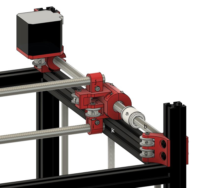
Relative to this image, left and right is the X axis, forwards to backwards is the Y axis
- The joiner has to be mounted to the Y rail Bushing (a) which is around the Y rail (b).
- Move Y rail to accommodate for the space and tolerance needed.
- We now have a middle plane to base components above and below.
- A GT2 Timing belt needs to run through (c) from (d) to (e).
- Enough vertical and horizontal space needs to be accommodated for a GT2 Timing belt to pass through (c).
- The belt is passed around the drive pulley at (d) and fed back to and around the idler pulley at (f) .
- Incoming belt coming from (g) runs to and around (h).
- The idler pulleys at (f) and (h) should guide the belts to be directly above one another.
- X axis bars mounted above and below at (i) and (j).
- The entire assembly has to be far enough away from the aluminum extrusion at (k) so the mount at (i) has enough clearance.
Some other things to keep in mind are that I am using M3 nuts, all belts should be kept level and square to one another, and bolts to assemble things and I have decided completely after thin air with no idea if this is right or not that a 3 mm thickness for parts should be kept, minimum, for structural stability.
The way I went about making sure I followed the logical design above was like this. I would design the parts as far as I could, bring them all together in the main build file with the frame, put them in the right places, measure distances from one another, find out where I can change based on my constraints, then change that and continue designing. An example of this is like for the pass through hole at (c), I know the GT2 Timing belt is 6 mm tall, so I should give it a couple mm of space on either side. This leaves me with a ~10mm square hole accommodated for that belt. That means those platforms need to be at least that distance apart. Once that hole is placed, I know my belt should go right in the middle of that, so I position the motor and drive pulley at (d) to match that exactly. Now that the motor and drive pulley are in place, I know where the belt will come off that pulley, so I know exactly where to place the next idler pulley.
It really is just a cascading table of logic and measuring. Of course there are things I missed in the process or didn’t think about initially. I had completely forgotten where the aluminum extrusion was and the part completely intersected in space with the frame, forcing me to redesign. But hey, that’s all apart of the process.
This idea of cascading logic continues to the other parts, of course. Should they not adhere to the logic sequence that we have already used to design the parts then nothing will work together as we expect them to. Thus, during the entire process of designing this one part, I figured out the important dimensions for practically all other parts in the system. It was a lot of work initially, but once I got it, the rest of the parts were a breeze to make.
More detailed pictures at the bottom of this page.
Design Mishaps
Unfortunately, upon the completion of my design of this part and the following parts, I realized I was going about this design wrong. Obviously I wanted to maximize space available to the printer, but I had such tunnel vision to maximize space out of the X axis that I completely sacrificed the Y axis.
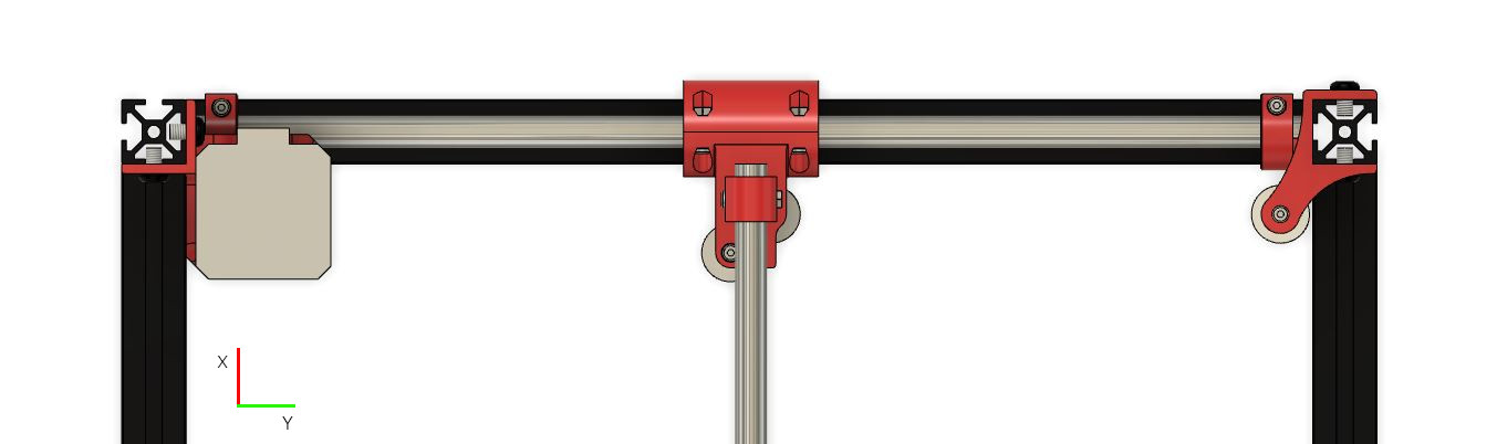
The stepper motor is the real villain here, taking up so much space, around 42mm. I had initially elected to have the stepper motor to the right of the aluminum extrusion to free up its ability to move in the Y axis to accommodate for the XY Joiner. That just flat takes off 42 mm from the Y axis. Not only this, but for reasons unknown besides shortsightedness, I placed the idler bearing mount on the right on the inside of the frame. This is completely unnecessary since it sits above the frame. This costs me another ~20 mm of space in the Y axis.
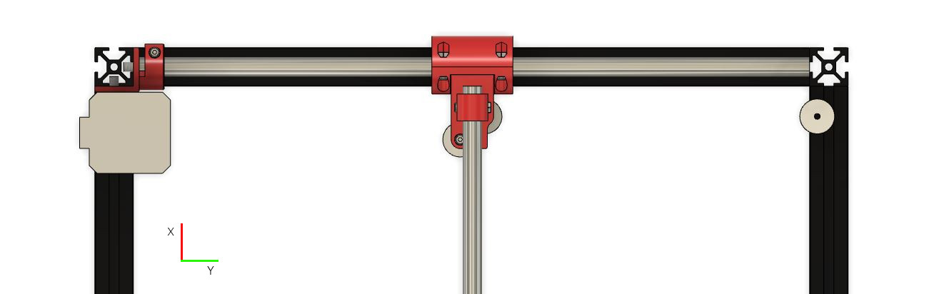
We can instead tweak this design to be significantly more efficient. I can mount the stepper motor to the bottom of that vertical piece of aluminum extrusion to the top left. I measured it out and it would only have to move about 10mm in the X to make that change effectively saving probably up to 30mm of space. Same thing, but on the other side for the idler bearings to the right, nudge those over and that’s a little extra free space. These changes are great, shifting the limiting factors of this design from the bulky motor and bearings to instead the mounting of the rod itself. This would be significantly more efficient than the current design.
Pretty dumb oversight, so making these changes are my next goals before going any more in depth about them. Thanks to the non-destructive, procedural base of Fusion 360, it should be relatively easy to change the XY Joiner. I will probably just remake the other parts from scratch since they are pretty straight forward.
More posts to come on this part. I will have more detailed views of the other parts in this system as well as the rest of the printer in future posts once I finalize their design a bit more!
Here are some more pictures for this part.
Construction Order


Views


Everything Measured and Lined Up