Last post I went over the snap clip design for the XY Joiner. This post will be covering the print bed assembly I came up with. I had quite a few problems with this design mainly stemming from determining what kind of heated bed I would have for my printer. Once I knew that I could get final dimensions and figure out spacing to fit that, but without it I couldn’t really safely start preparing materials and printing parts, so this was the last assemblies I made. This post is structured in a big block of research for heated beds (feel free to skip because the design and construction are more enjoyable to read), the design for the assembly in fusion 360, and the actual construction of the assembly.
AC vs DC Beds Research
I was conflicted on what style of bed to get for my printer, they re easily broken down into 2 groups, AC and DC powered. They both have their advantages and disadvantages and vary significantly in price. I personally ended up going with a DC powered bed due to the circumstances of this specific project, but would like to upgrade to an AC bed in the future. For reference, this post and video from Tom’s 3D is a great explanation of print beds goes over a lot of important information.
AC Powered
Advantages
AC powered beds use alternating current power directly from the wall outlet. This offers 2 huge advantages, they are very energy efficient and heat up very quickly. The power supply’s job is to convert AC power from your outlet into DC power that is used in your motherboard for computations. This conversion results in a certain amount of power loss. Typically this will be around 70-90% efficiency. Now I’m not an electrician or anything, so don’t take my word as gospel, but my understanding of AC power is that you are able to use a much higher voltage (Here in the US mains voltage is 115V) and lower amperage and can easily achieve a high wattage without any of the power loss to DC power (I also believe there are problems with pushing that much DC power through to heat up while AC power can do it better, but I can’t really remember where I learned that, it feels like an educated guess from what I know about AC and DC power). Typically you would want around .6 watts/square cm (suggested by Toms 3D), so as you get a larger print bed, you need significantly more power to heat up such a huge bed. By using AC power you can very easily hit these power requirements and still heat that bed up very quickly.
Disadvantages
Now AC powered beds also have some pretty significant downsides. You can’t just connect AC power to your motherboard, it would blow it up, so you need special electronics to control them with your regular print board. This also leads into the bigger downside, AC mains power from your wall is EXTREMELY dangerous. It can definitely kill you or cause a fire if something is not properly wired. Ensuring you have proper safety requirements and that your electronics are in proper spec is extremely important. It is very important you ground the frame of your printer to ensure you are not electrocuted if something goes wrong. you have to be very diligent and invest in a good quality controller to ensure its performance. There are plenty of cheaply made parts that are easy to go for, but it’s important to get quality stuff for this.
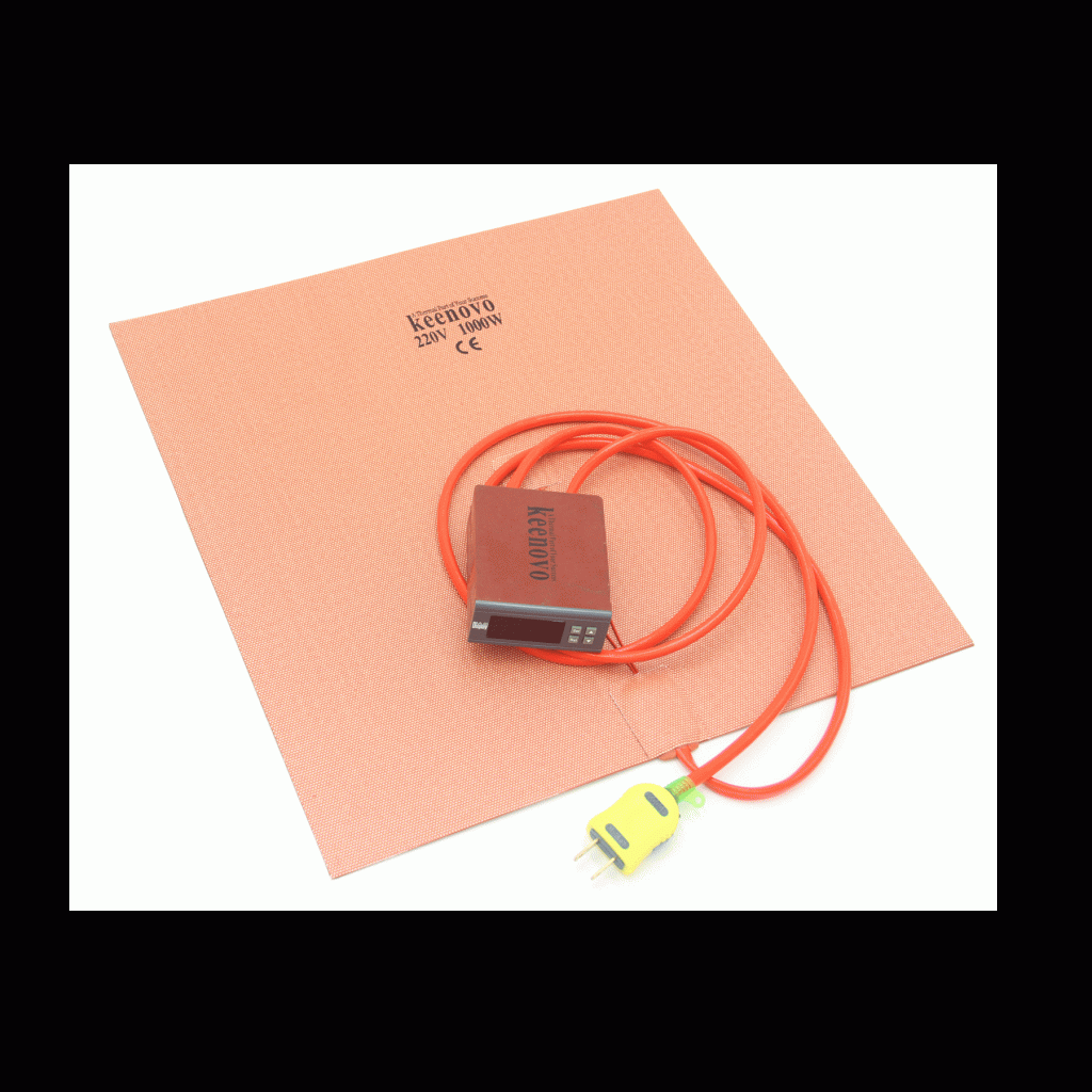
Typically AC powered stuff will be more expensive too. Typically you will need to get a silicone heater and print bed separate. A good Keenovo silicone heater that’s 280mm square costs $105 and you still need to source the actual print bed. Finding these to fit custom to your printer can be super annoying and tedious. We already talked about researching a quality controller for it I would have gotten an AC powered bed but it was much easier for me to just get an all in one package DC powered bed and that convenience and lower price point was enough to make me cave.
DC Powered
Advantages
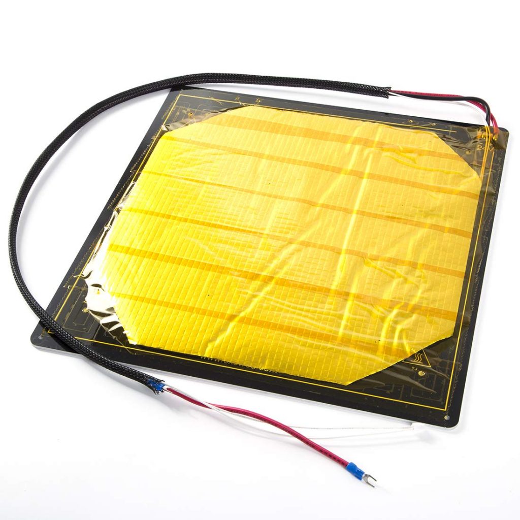
DC powered beds require a capable power supply unit to run. They are very standard online, much easier to find, and cheaper. They are plenty reliable and easy to use. Typically these come in easy and complete packages with a print bed and can easily be directly connected to your motherboard. These beds are tried and true, they typically come in 12 or 24 volt versions depending on what the rest of your printer is. Pretty straight forward. The bed I ended up buying is actually a Creality CR-10S Pro bed replacement so it was so easy to find a quality product that I knew was going to work well and at a $53 dollar price tag it was an easy deal. Its 24v 240W and plenty big, so it works out if my power supply holds up fine (Which it should).
Disadvantages
DC power obviously has its disadvantages. We’ve already talked about some of them in AC power but it boils down to this, they are less efficient, take longer to heat up, and are better suited for smaller beds. Depending on your power supply, it can be hard to hit that typical .6 watts/square cm for your bed (suggested by Toms 3D). You may have a 12 or 24 volt system and Watts are Volts x Amps, so if working in a 12 volt system you have to have twice the amperage to reach the same wattage of a 24 volt system. This isn’t that bad though, just ensure you get all 24 volt parts, but this requires forethought and if you are looking to upgrade a printer you already have that can make things harder. They do relatively take long to heat up though, AC powered beds are pretty damn quick, heating up in probably under a minute, but realistically this isn’t that ridiculous as most DC powered beds take 3-4 minutes max, that time isn’t that important when you are printing for 10 hours. It is harder to print with bigger beds with DC power, just means you need more amperage which means a significantly beefier power supply to deal with it which can start getting pricier. More than likely though, this won’t be that ridiculous if you are able to source a good power supply, they aren’t terribly hard to find but you will want to look for one where your total power draw will only be around 60-70% of its max capacity, you never want to use power supplies to their maximum values.
Assembly
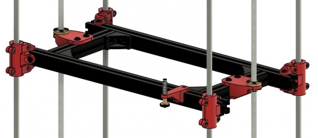
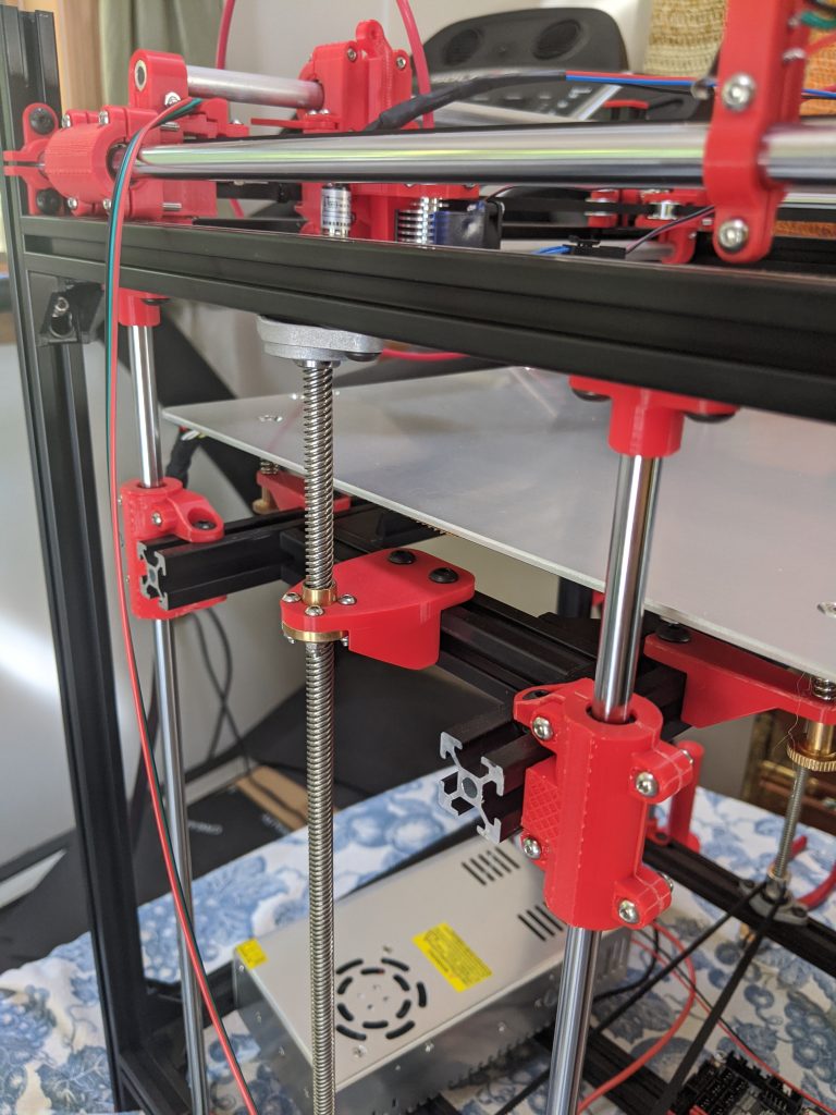
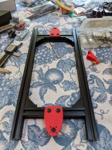
In an earlier post I talked about some examples and my logic behind the Z axis system I decided to use. With 2 lead screws and 4 linear rails I am going for a nice and sturdy bed. I didn’t want a bed that would eventually sag over time, there are many cantilever bed designs out there but I can’t help but think that they will quickly deteriorate in the longer run. I had to accommodate 6 mounting points on my bed mount, so I went with a simple rectangle with arms.
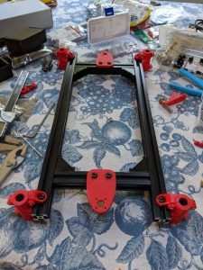
This design allows for a very rigid frame of extrusion enforced by aluminum corner brackets. With some logical designs I managed to get everything measured out to mount the lead screw nuts and linear bearings in tight tolerance. The arms of this rectangle extend to sit on the inside of the linear rails. Keeping it on the inside gave me plenty of space to extend outwards depending on what size bed I was going to get. Why does this matter? It doesn’t really, it only sits there because of where the linear rails are. Why are the linear rails where they are? Because having the bars separated by 100 mm felt nice. No other real reason, could have probably made a more informed decision here, but it didn’t feel like it was that important in the grand scheme of things so long as it fit and made things easier. When you can, use nice, square numbers.
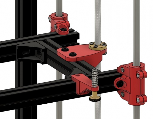
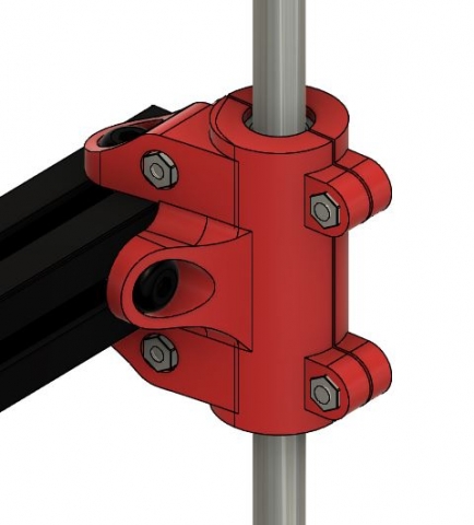
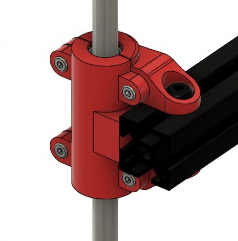
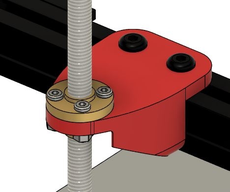
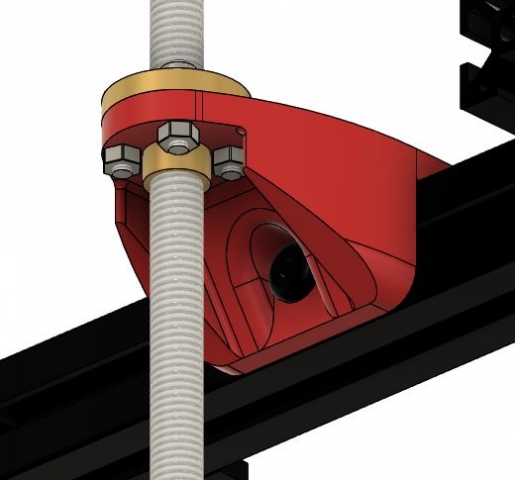
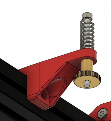
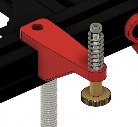
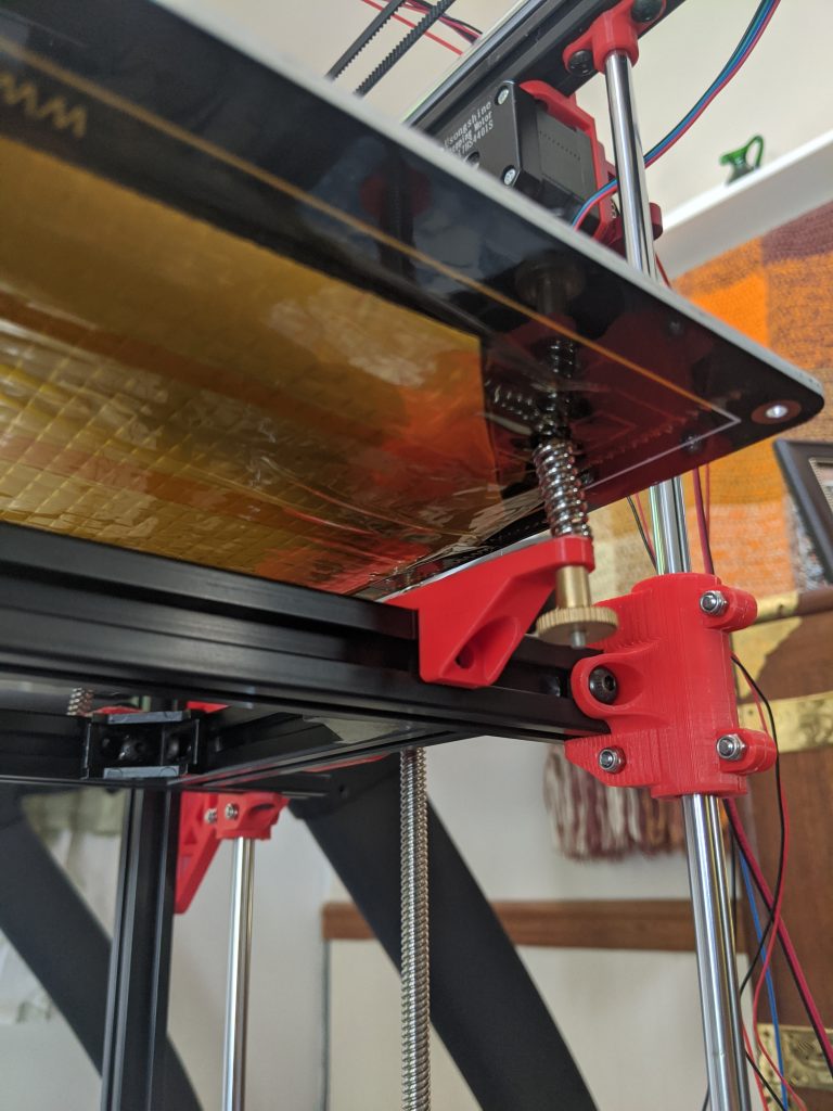
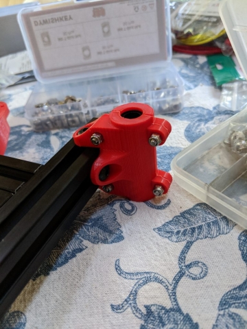
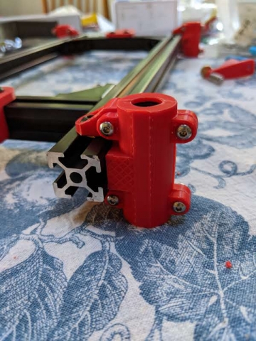
The bearing mounts aren’t the most elegant design, to be quite honest I was running out of steam as I was designing and just wanted to get it done. It be like that sometimes. They are simple enough mount and clamp designs around LM8LUU linear bearings. The nut mount is also simple, just making sure it fit the nut (I ended up just drilling it out and the nut fit great) keeping some strong mounting points. The bed screw mounts had to be properly sized for exactly what my bed’s holes dimensions were so everything would line up. Simple enough, they just allow a place for the screw and spring to go through.
Construction
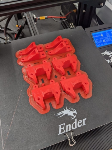
Constructing this beast was a whole other process. For some reason this print gave me some grief so I just gave it a big ole brim and cleaned it all up after.
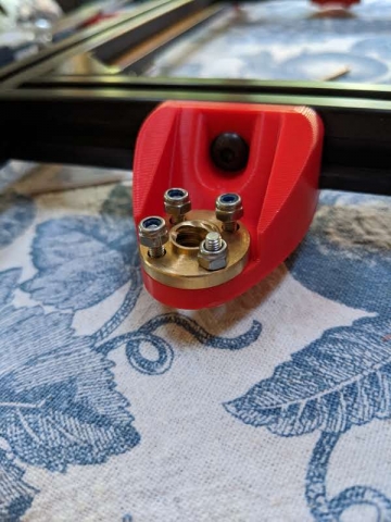
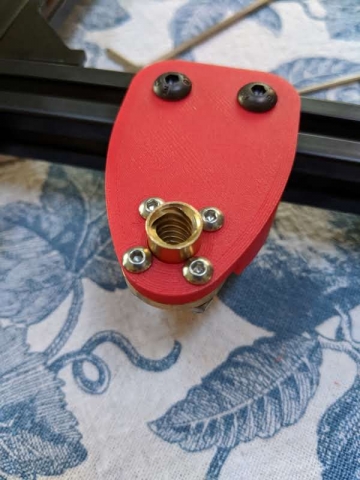
The pieces fit together pretty well. I ended up cutting the extrusion for the arms a little long, I think I was just scared I was going to mess up and be annoyed it was a little too short, but this kind of just looks weird too. But what’s done is done, with these things it will more than likely never be changed. The nut mount fit cleanly and with 4 screws with nyloc nuts will keep it firmly in place despite all the movement.
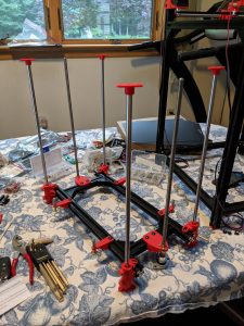
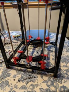
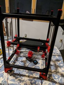
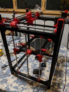
The frame was easy enough to put together and off, once it was together this thing was plenty sturdy. I popped on the mounts and fit them into the correct place, no problem. From there on I was very careful to insert the rods and lead screws and keep everything as straight as possible. The linear rails were press fit into mounts I printed and the leadscrews were secured in bearing blocks. It was very easy to have something twist off to the side and I wanted to be careful to not damage anything. These linear rails and lead screws were pretty tough, but I took it very slowly. One by one I maneuvered the rods into place. It was very anxiety inducing, but I ended up getting there. I screwed it into place and flipped it upside down to get the top screws in place. Just like that it was all together and moving great! I didn’t take the time to perfectly align everything, I’ll be saving that for the future.
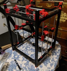
All in all the print bed was very satisfying to get together finally. It feels very very sturdy and moves very cleanly up and down. The parts weren’t very complicated, but the research was tough for finding the heated bed to fit my needs. Next post I will go into the mount for the motor for the Z axis and my process for splicing a GT2 timing belt for driving the Z assembly.

