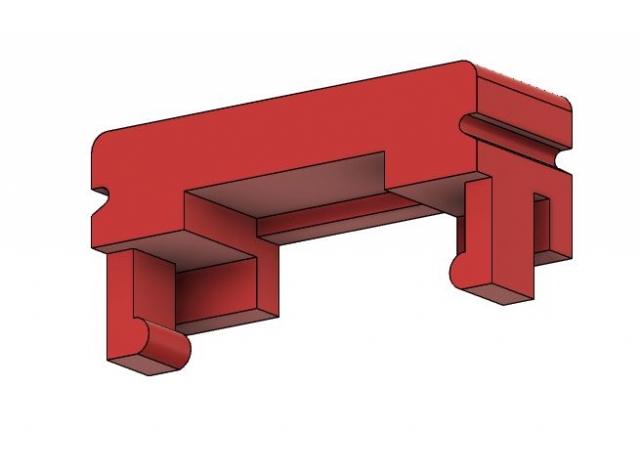
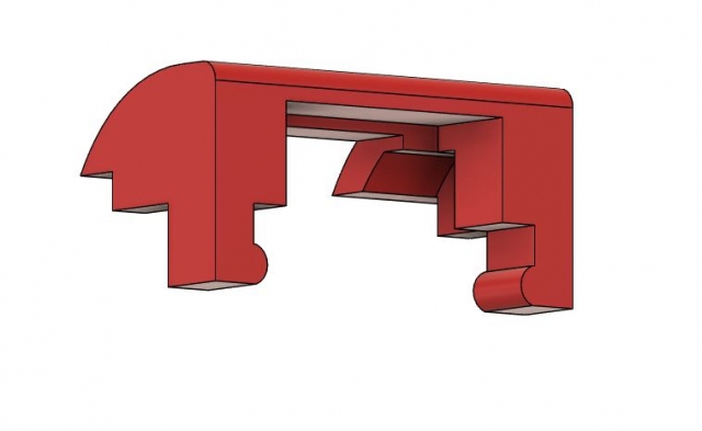
Last post went over the E3d mount and this post will go over the snap-clip hardware I designed for the XY Joiner. It was fun to get some experience with this style of hardware, it can really help create a cut and clean product. It would be fun to make some cases in the future that are a one time clip to push fit some pieces together completely seamlessly and take my design to the next level. I need to test some more plastics too because PLA couldn’t take the continuous deformation and eventually gave out on me. It will work fine in this case, but it would be really nice to have a good handle on this style of hardware to be fluent with it in the future.
When designing the Endstop Mounts I realized I had a bit of a problem for the X endstop. If I were to mount the whole endstop to the bar it would be pretty bulky and disorderly. I would be concerned with the board getting damaged from not being mounted properly. Also it just doesn’t look good at all. Can’t have that.
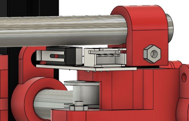
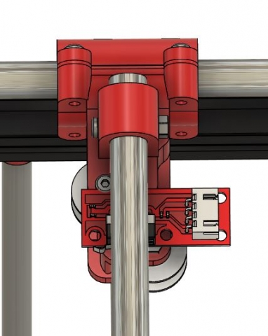
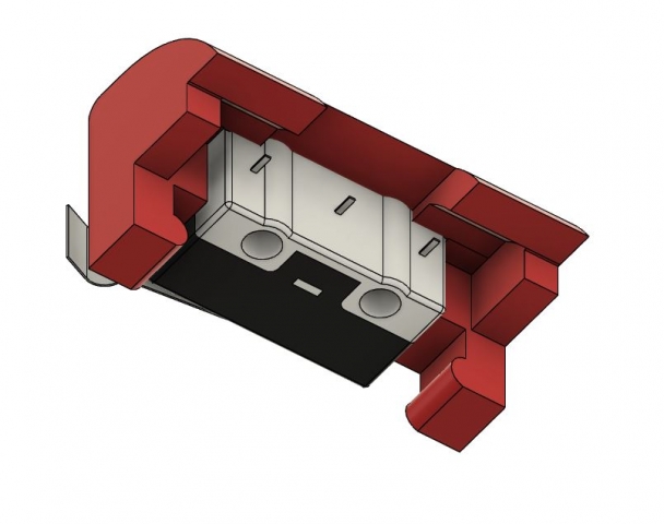
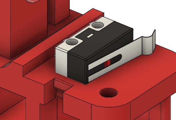
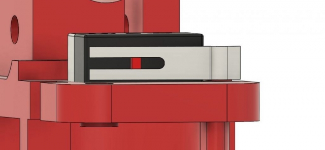
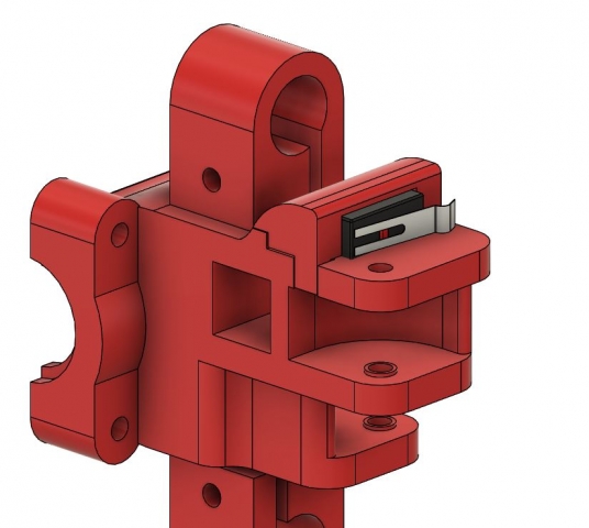
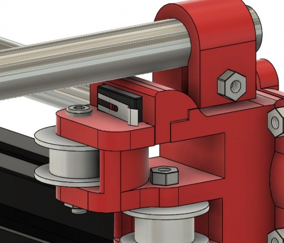
It was obvious to remove the microswitch from the endstop board. To separate them and run the wires to the board mounted elsewhere would save a lot of space. There was enough space to put the microswitch between the XY Joiner and the top X aluminum bar, so that’s where I put it. It’s definitely possible to find a way to mount this with screws, but it seemed a bit unnecessary. After a bit of research, it seemed a snapclip design would work pretty well in this instance. It doesn’t need to withstand a ton of force, but still has to hold steady.
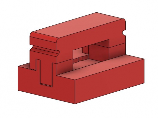
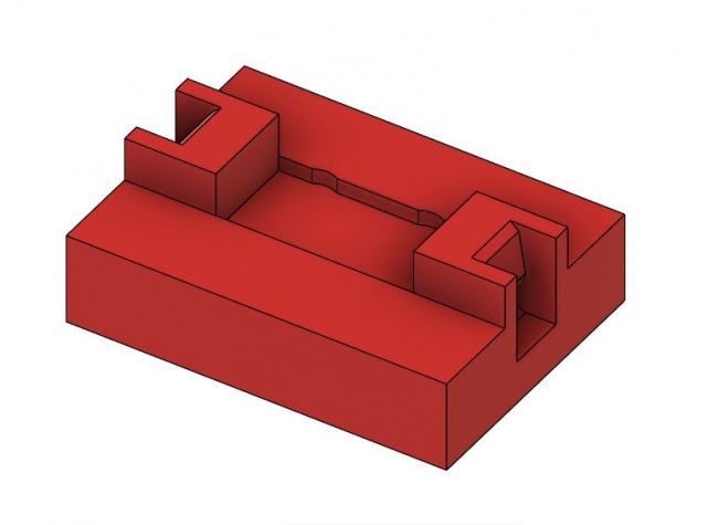
I went about making a little tolerance test to figure out a good design to fit the microswitch. It took a bit, the biggest problem was getting the arms to have a deep enough angle so they would grab, but shallow enough that they could eventually be removed too. It doesn’t have to be removed often at all, but still has to be done eventually. Once I got those tolerances nailed down after a couple of prints, I was able to just copy the dimensions for the most part.
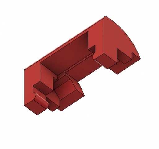
Actual snapclip
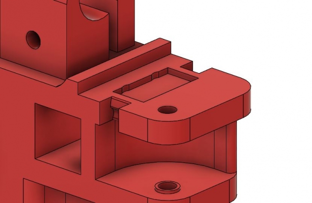
The Cap itself is pretty much the same, but with a couple extra tweaks. There is some space inset into the XY Joiner to keep the microswitch stuck in place as well as a little gap behind the switch itself as well to solder and feed wires out of the Cap to the board. I also included a little lip in the XY Joiner that matches with the Cap to ensure the pieces fit snugly together. It was tough ensuring there was enough space and designing 2 pieces to fit together like this, but I was able to eventually get them to line up quite nicely.
All together it looks pretty clean and sleek. I talked in both the X Carriage post and the XY Joiner post about these two working together to line up properly and poke the microswitch with a mountable arm on the X Carriage. My biggest concerns with this design are that it won’t be able to hold or will eventually loosen and fall off. Depending on how it goes in my tests I may end up reprinting the cap so it is braced against the aluminum bar or wraps around it to ensure it stay there sturdy. Probably should have done this already……but I don’t want to redesign again for now.
Next post will be about the print bed assembly, it was one of the last things to be completely designed because I wasn’t able to find a print bed that fit this printer. It was tough and I’m not completely happy about it, but it can be upgraded eventually if it ends up being too annoying.

