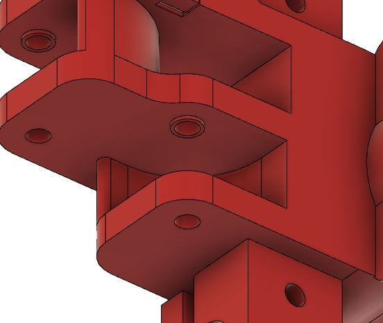
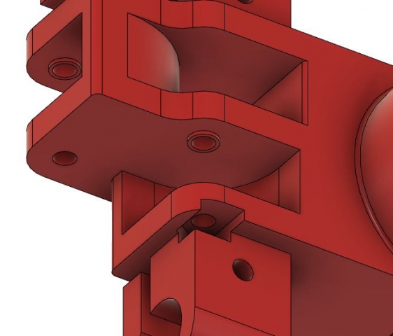
After a brief hiatus, I have returned to designing my printer. Thanks Corona Virus for freeing up my schedule…
In my last post I detailed my design process for the XY Joiner. This post will go over the new XY Joiner as well as briefly touching on how it fits into the newly designed XY Joiner assembly.
The original assembly worked, but was not as efficient as it could be. I detailed some changes to extend the Y axis by shifting some parts around:
With my newfound free time I have since redesigned this entire assembly. Another of my problems with the assembly was it was a bit overzealous, a lot of the design was over complicated and could prove to be significantly simplified. So I designed the end mounts to be a little more streamlined, making them quicker and easier to print.
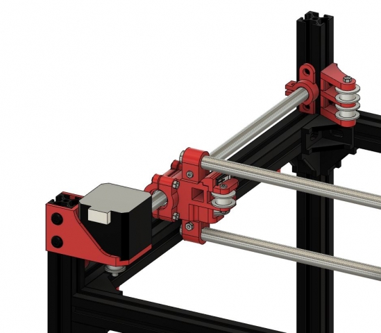
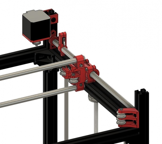
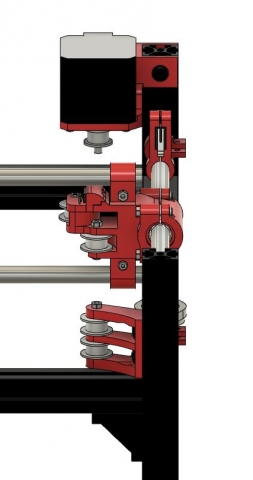
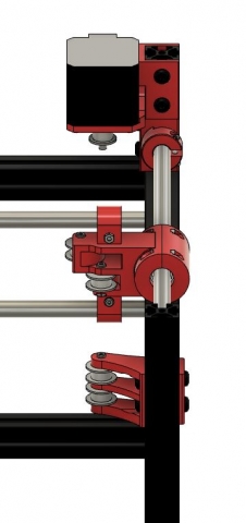
Here’s the current assembly:
The bar mounts and idler pulley mounts have been simplified and separated. Many changes have been made to the XY Joiner itself to incorporate the shifts to more efficiently use space. More mounts have been designed to incorporate the end stop switches in optimal positions.
The biggest changes to the XY Joiner were moving it to match the new position of the belt and building in a mount for the X endstop.
The entire assembly has been shifted out a bit to meet the new path of the belt set by the new motor mount.
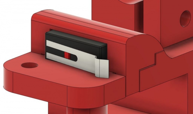
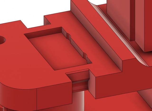
After some experimenting and designing, I found that with the limited space available to fit the X Endstop in, I would design a small snap clip assembly to secure just the switch, then run the wires out the back to the circuitry. The mounts for the bars have been shifted back to allow more space for the end stop mount to be built directly into the joiner.
This was a bit of a process to find a design I liked, that was secure enough to hold the tiny switch, but also easy enough to pop on/off (not that it necessarily has to come off, but come on, ease of use). If you want a more detailed breakdown of the process for developing snap clips and specifically the mount for this use, check out this post.
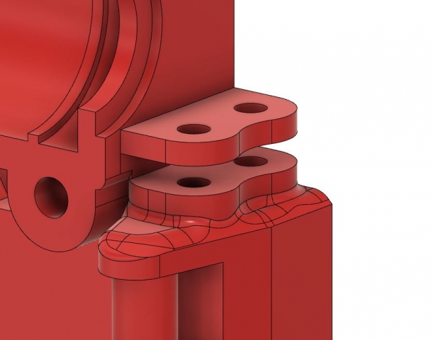
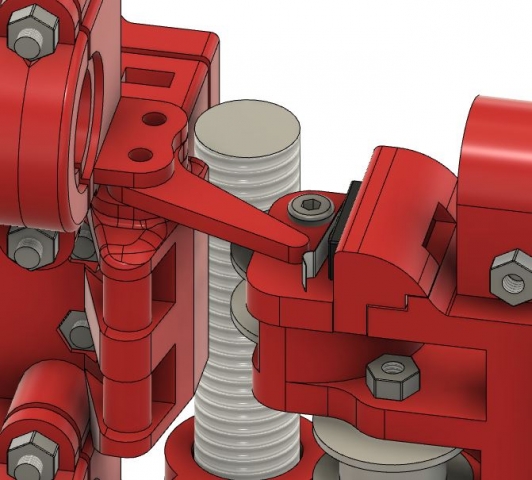
This endstop switch sits securely, but obviously recessed from the bounding box of the XY Joiner itself, so the X Carriage won’t be able to naturally hit it. Thus changes were needed to be made to the X Carriage to accompany this. I designed a little area for an arm to be attached. I was worried on what length to make it and didn’t want to be stuck with that length in case it were too short or long, forcing me to reprint everything. This little mounting point was perfect, I could change the arm size if I need to.
A couple other changes to the XY Joiner that should be mentioned:
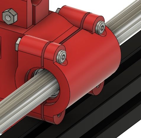
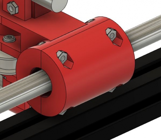
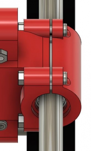
I changed the mounting cap to be a little less clunky and more streamlined. It’s a lot slimmer and cleaner. I initially thought to put the bolts on the XY Joiner itself and put the nuts on the cap, but I found I couldn’t design a structurally sound enough print to hold the nuts in place like how I did in the original design. It made the entire design unnecessarily complicated, so I simplified.
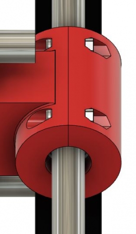
I changed the bushing mount side to be a bit thicker and have a sliver taken off its base. This just gives me some free space to clamp down onto the bushing to ensure a tight fit.
A pretty severe oversight has also been fixed. In the original design it was impossible to put the bolt in for the bottom idler pulley to rotate on thanks to my ingenious logic. This has fixed itself since I moved the top and bottom bar mounts back, allowing a lot of extra space. Stupid oversight, but it’s been fixed now.
I also removed all the insets for the bolts and nuts, they were totally unnecessary and severely over complicated the print. It can be hard to realize the scale things actually are when looking at it through an orthographic view on a computer screen. I have a little more experience now.
I’ll detail the new mounts, since they are all relatively simple but for the most part have significant changes, in the next post!
