
In my recent design overview I detailed the dimensions for the aluminum extrusion frame. I will be going over the process taken to cut the frame to ensure they are as equal and square as possible. This is definitely a bit overkill, but hey, if I have the opportunity to, why not go for it? Thanks to my Father for his tools and expertise!
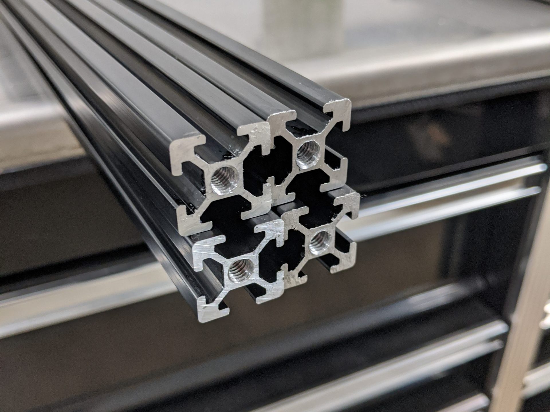
As detailed before, I need 4 x 550 mm pieces for the uprights and 8 x 350 mm pieces to connect them. I ended up getting my aluminum extrusion from ZYLtech. One thing I found was very important when looking for aluminum extrusion was ensuring the dimensions work with other hardware. Companies like 8020 have great aluminum products, but their dimensions typically only work with their own hardware to assembly it. You couldn’t just order some third party hardware on Amazon to work with it, so it’s important to know it would be harder to find hardware for that kind of stuff. After checking dimensions with some other parts on Amazon, ZYLtech aluminum seemed to be pretty universal.
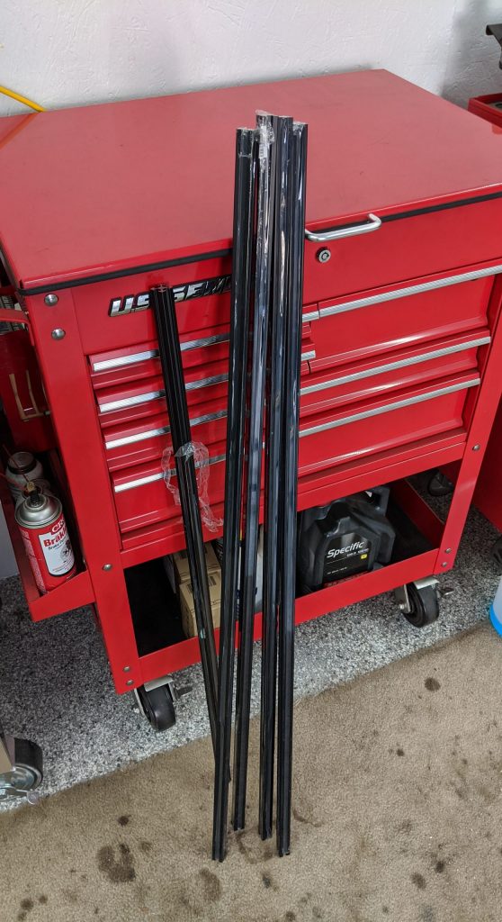
ZYLtech sells the aluminum extrusion in various precut lengths. To get my pieces for the cheapest possible, I got 4 x 1200 mm pieces and a 1 x 1000 mm piece. This stuff was great quality, I have no problems with it, it was very straight, exact lengths, I’m very happy. I also totally sprung to get the anodized black aluminum, I gotta color coordinate and I know I would be annoyed with myself in a year if I didn’t get the stuff I wanted.
So when cutting this extrusion I had 2 options. I had access to a metal band saw and a miter saw:
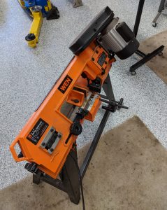
I wanted to ensure the cut ends of the aluminum was as clean as possible, so we cut some test pieces to check the quality. The metal band saw was a bit aggressive and left the end a bit jagged.
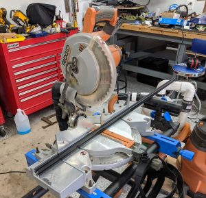
Not that it couldn’t have been cleaned up, but the miter saw cut practically completely clean, so let’s go with that.
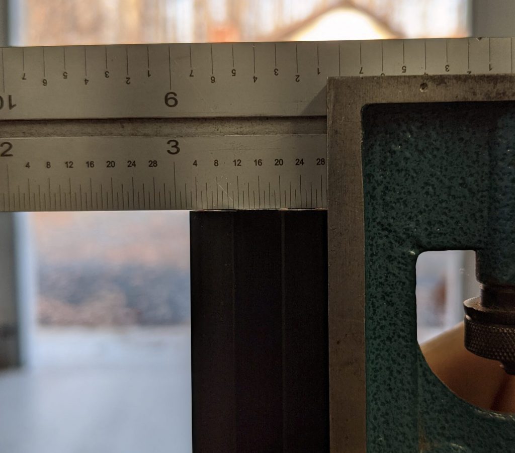
After some time honing in the saw to be as exactly square as possible, checking squares to see how square they were, then adjusting the saw all over again, we got to something that is pretty damn square. Don’t think we could have cut much more square or precise with this tool.
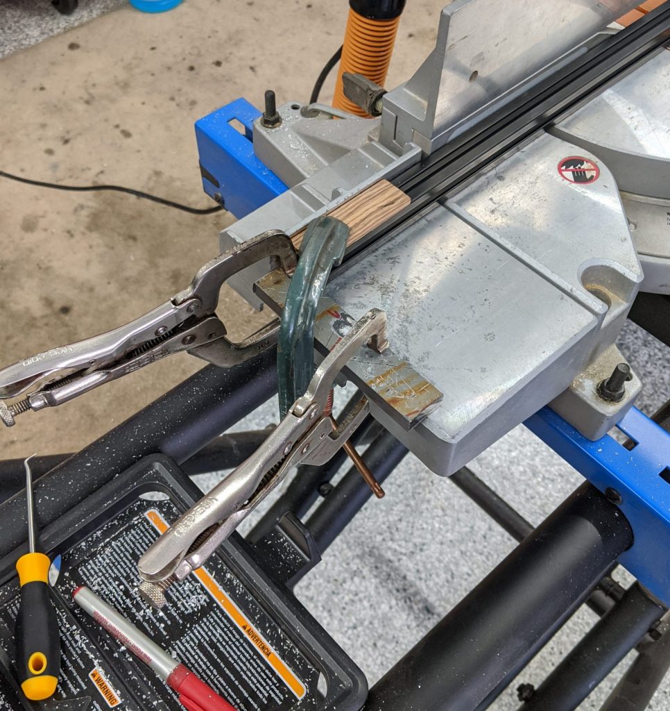
To make exact cuts we ended up clamping a piece of scrap metal to the miter saw to ensure exact lengths between cuts. It was more important for the pieces to be exact to one another then accurate to dimension. This is to ensure the frame is perfectly square which is pretty important to keep all the kinematics precise. We also discovered that it was important to clamp down the aluminum rather than just holding it by hand. There would be inaccuracies in the cut thanks to the vibrations from the tool, so a quick clamp with a random scrap of Zebra wood that happened to fit perfectly and problem solved.
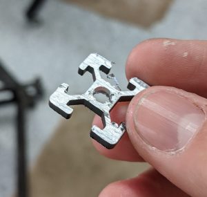
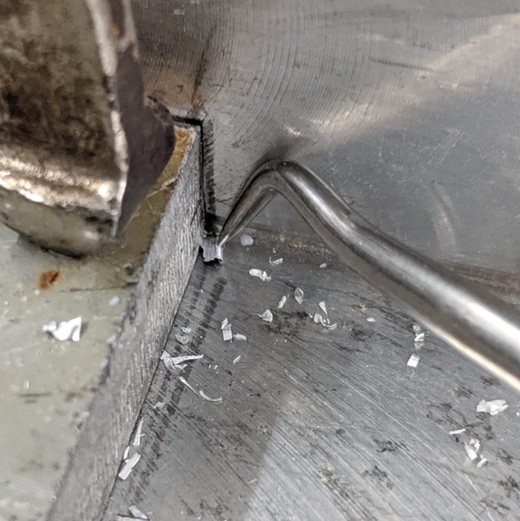
Between cuts there would be some little chips of aluminum that would find their way to the end clamp. When putting the next piece up to be cut these little chips made a significant amount of a difference. So we made sure to pick out all the little bits in-between cuts.
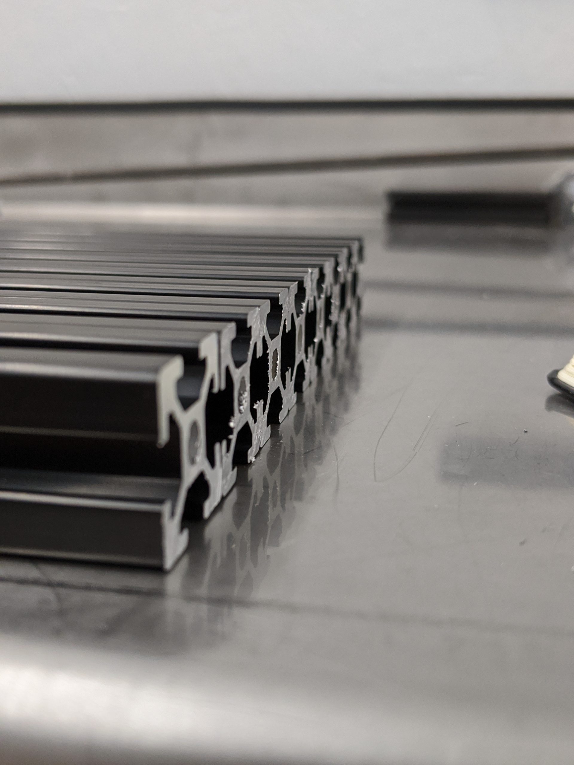
After cutting all the pieces, I lined them up to check their lengths against one another. They were all completely the exact same length. Setting any two of these against one another and you would feel completely flush ends.
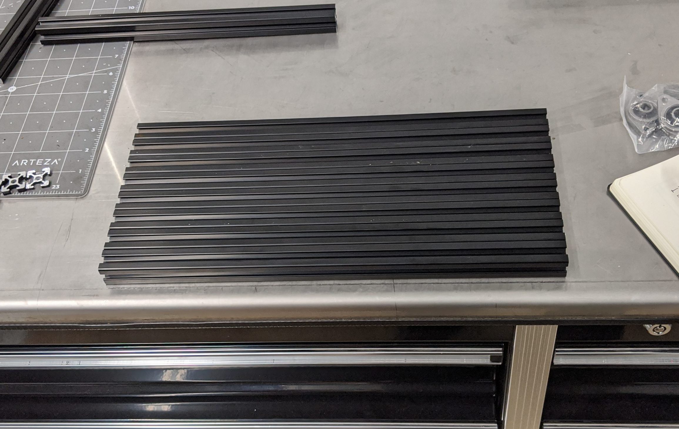
Couldn’t be more happy with the outcome even though it took a bit of work. We also took the liberty to tap the ends of the 550 mm uprights since those ends would be exposed. It’s nice to have that flexibility to screw stuff to the end whether it be for feet on the bottom of the printer or to mount something to the top.
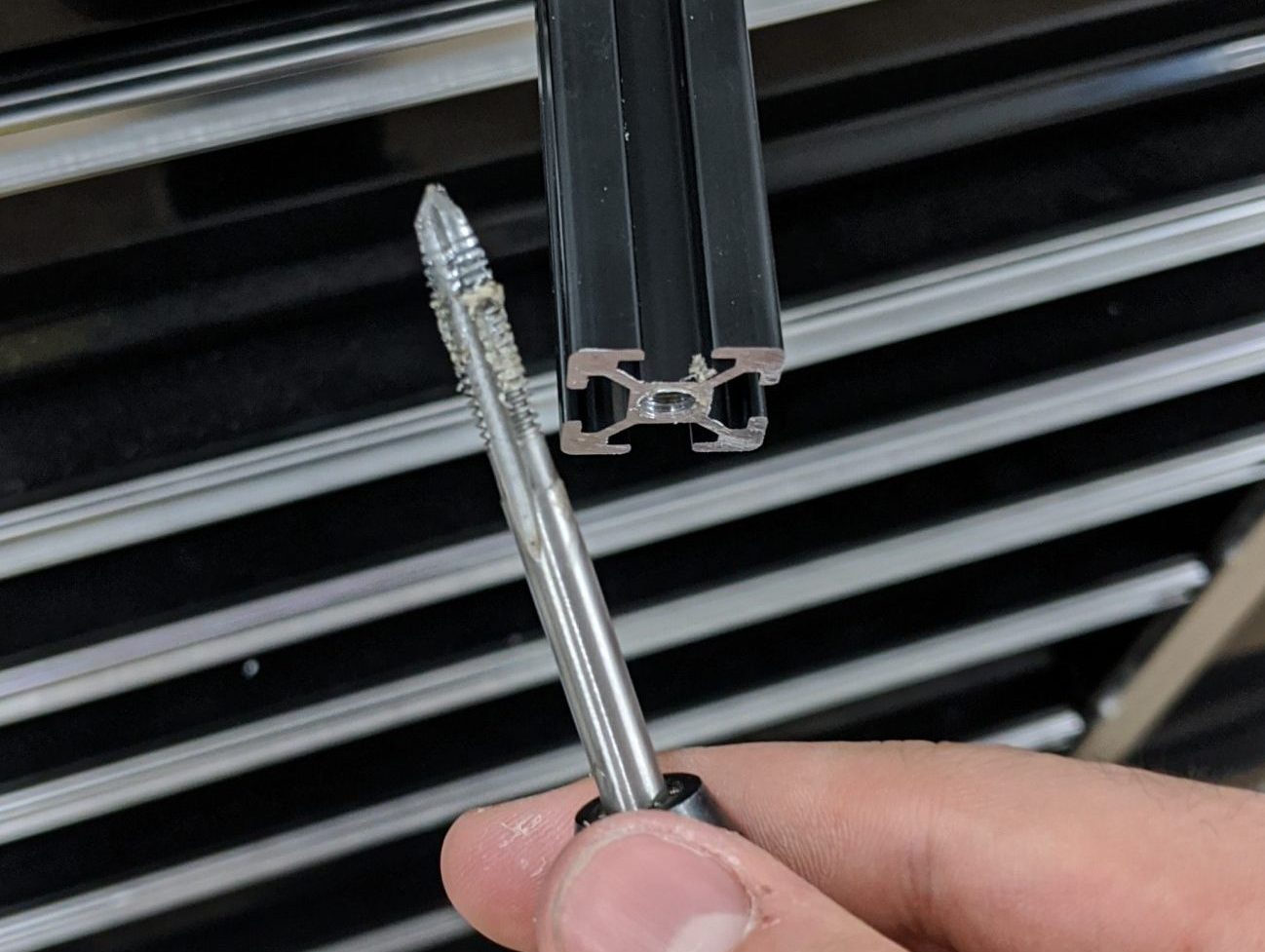
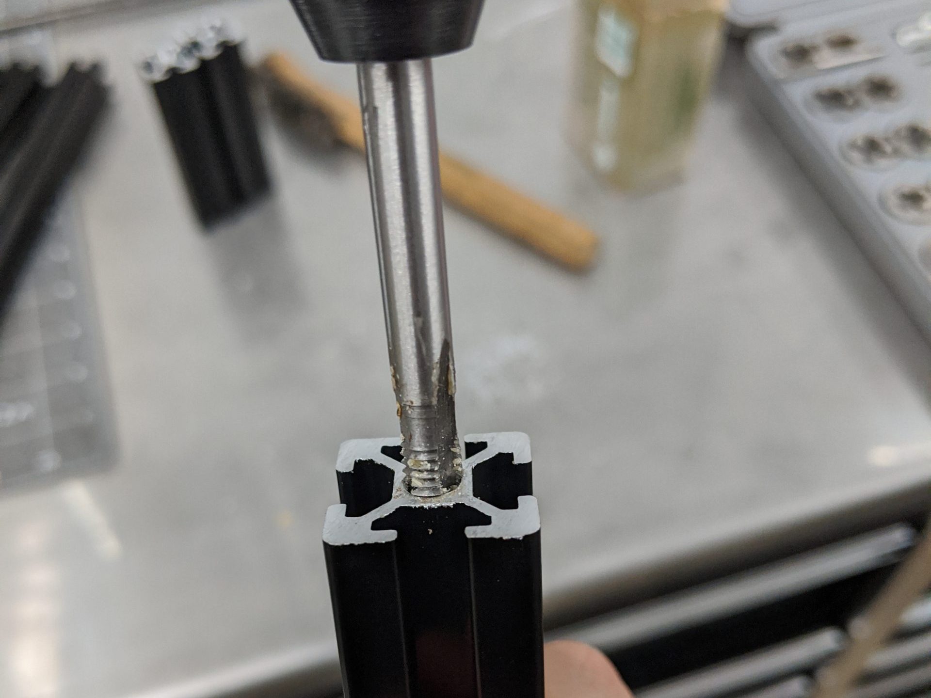
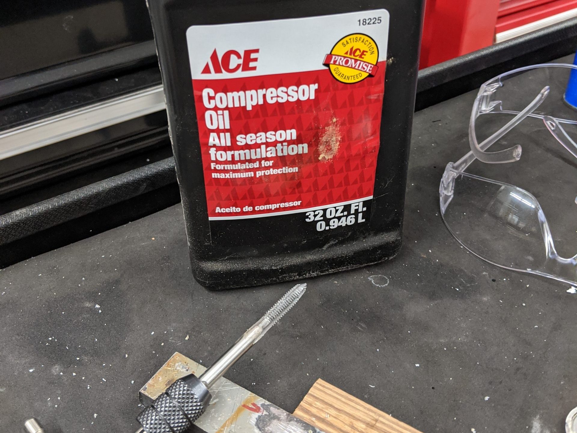
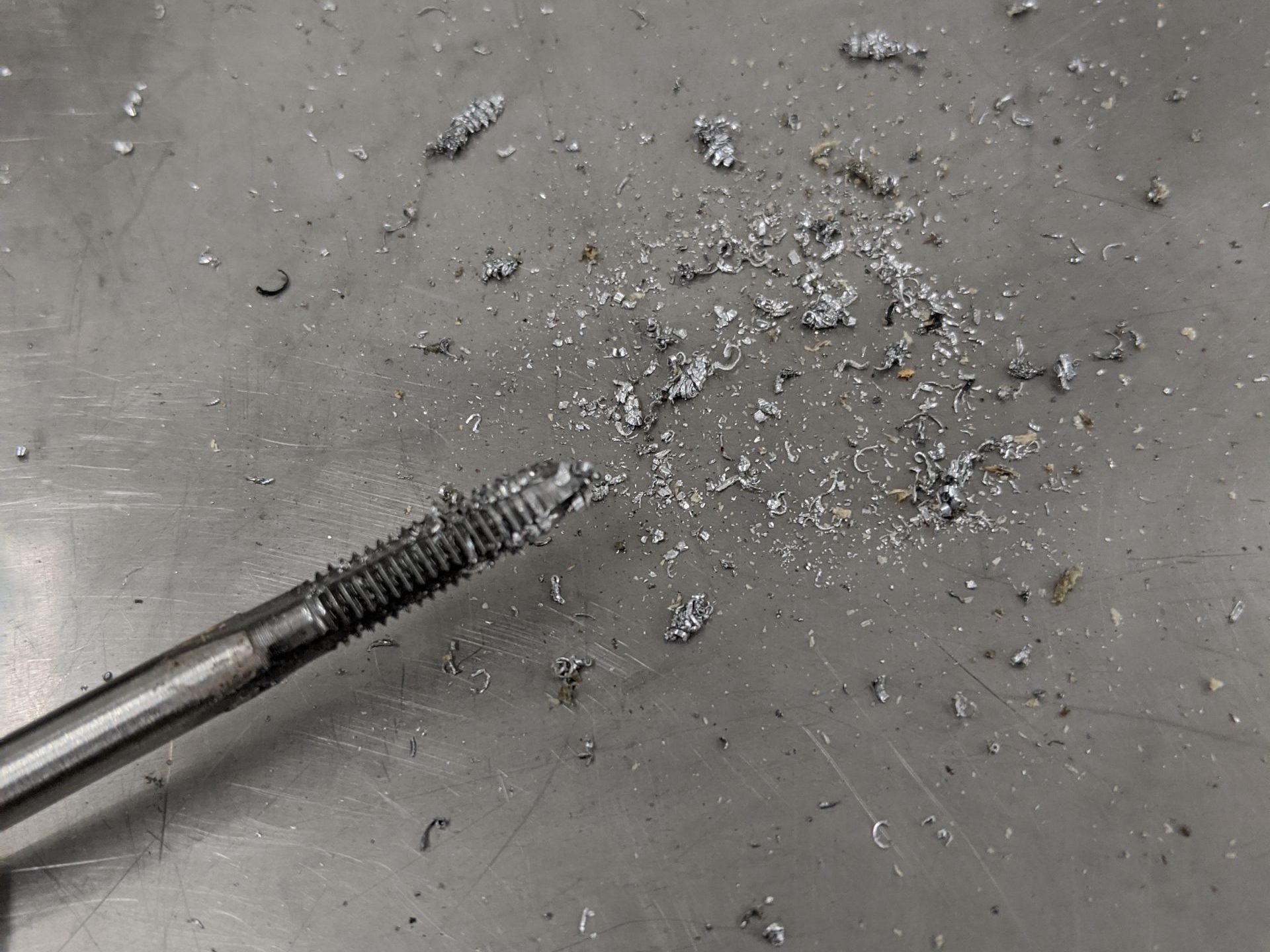
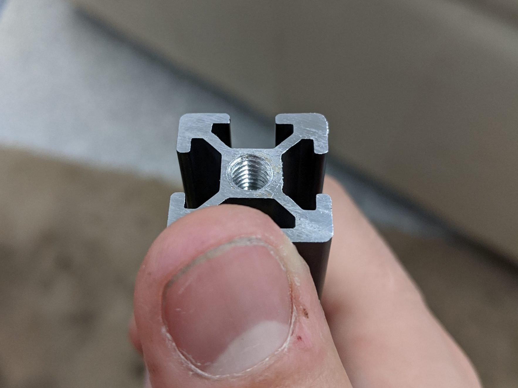
Simple enough, just used a little bit of compressor oil to lubricate and took maybe 5-10 minutes to tap all 8 ends of the uprights. Not sure if I will use them, but it’s a good idea so I won’t have to come back to it later.
I had to haul all of this aluminum back with me on the bus to Brooklyn. Ended up plastic wrapping it like crazy to keep it all together and guard anything from the sharp edges of the aluminum. Now that I have these all cut and prepped, I can finally go about assembling the frame and start the actual BUILD in this build log!
At this time I have the majority of parts modeled in Fusion 360, so I’m excited to start going over the design process for those as well as the decisions I have made for my particular design. More to come next post….